Using a Normal Map in Blender: Node Setup, Flipping DirectX, Baking
In Blender, a normal map runs through its own Normal Map node between the Image Texture node and the Principled BSDF, color space Non-Color, convention OpenGL. Our `_nor_gl` files work as-is; DirectX maps need their green channel inverted first.
- Version
- Blender 5.2 LTS (currently 5.2.2, as of September 2026)
- Convention
- Blender defaults to OpenGL, our maps are `_nor_gl`
- Color space
- Always Non-Color, never sRGB
- Time
- 5 minutes to wire up, 15 to 30 minutes to bake your own
A normal map fakes small bumps, seams, and scratches without changing the actual geometry. Blender needs a dedicated node between the image and the shader, otherwise the Principled BSDF reads the color values wrong. This guide covers the setup for our finished _nor_gl maps, handling DirectX-style maps from other sources, and baking your own normal map in Cycles. For how the map fits into a complete material alongside Diffuse, Roughness, and ARM, see our Blender basics guide. For what a normal map actually is as a texture type, independent of Blender, and how it differs from bump and displacement, see our general normal map guide.
The Normal Map node
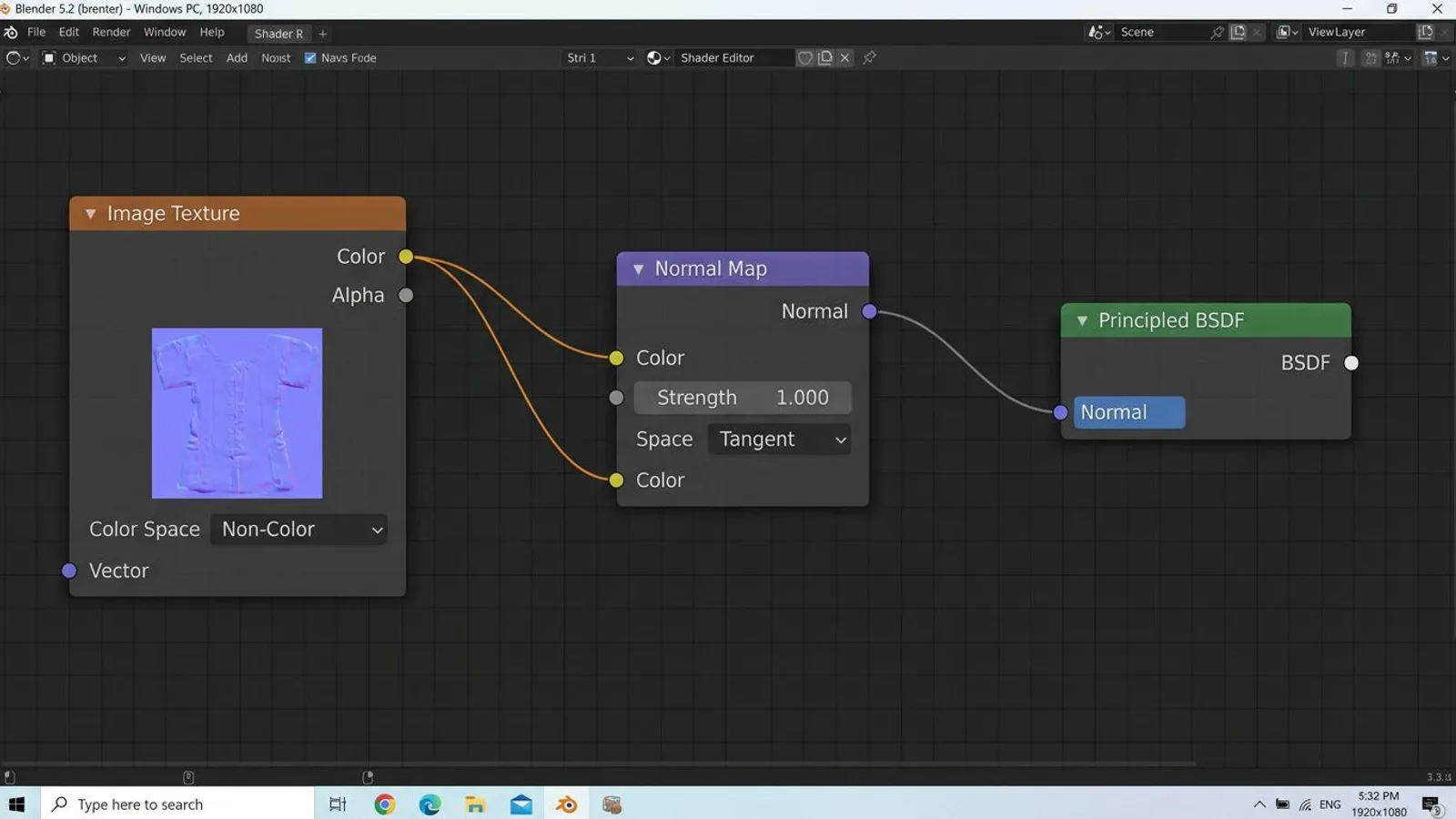
Never connect a normal map texture directly to the Normal input on the Principled BSDF, the result just looks randomly noisy. A Normal Map node (Add, Vector, Normal Map) always belongs in between. It reads the image's RGB values as a perturbed surface normal and turns them into a normal vector the shader can actually use.
The node has a Color input for the texture and a Strength input for how intense the effect is, defaulting to 1. Higher values exaggerate the bumps, 0 switches the normal map off entirely, handy for a quick before-and-after comparison while setting up a material. Values above 2 tend to look exaggerated on our textures and make edges look hard and artificial, so stay roughly between 0.7 and 1.3.
A further property, Base, only shows up once you're also working with real displacement: Original Base uses the smooth, undisplaced surface as its reference, Displaced Base refers to the already-displaced surface. As long as you're only using a normal map without displacement, this doesn't matter and the default works fine.
 AI-generated
Wiring up our map
Add an Image Texture node and load the file ending in _nor_gl, for example FSMW_rusty_corrugated_metal_01_nor_gl_4k.png. Set the color space to Non-Color, which the Blender documentation requires for a normal map, otherwise Blender applies a color correction to values that aren't colors at all, which distorts the direction of the normals. Connect the Color output to the Color input of the Normal Map node, whose Normal output then goes into the Normal input on the Principled BSDF.
On the Normal Map node itself you'll find the Space property, which almost always stays on Tangent, since tangent-space normal maps follow object transformations and mesh deformation. Object or World space are only needed in special cases, for example static geometry with no animation.
Also check the UV Map property on the Normal Map node if your object has more than one UV map. It needs to match the UV map the Image Texture node uses to project the texture, otherwise the normals and the color data drift apart and the bumps end up in the wrong place. With a single UV layer, which is what our models use, this isn't an issue.
Convention: why our maps just work
Normal maps encode direction in red, green, and blue, and there are two competing conventions that differ only in the green channel. Blender defaults to the OpenGL convention for rendering and baking, where the green channel points up. The DirectX convention, common in some game engines and older Substance Painter exports, points the green channel down, essentially a vertical flip.
Our _nor_gl files are deliberately built in OpenGL, which is also right there in the filename. Plug it in, set Non-Color, done, no flipping needed. The Normal Map node itself also has a Convention property that switches between OpenGL and DirectX, in case you ever load a foreign DirectX map.
Worth knowing if you carry your Blender scene into an LS25 mod later: the GIANTS Engine also expects normal maps in the OpenGL convention. Whatever looks right in Blender looks right in the game too, no changes needed to the green channel going from Blender to GIANTS.
Flipping a DirectX map
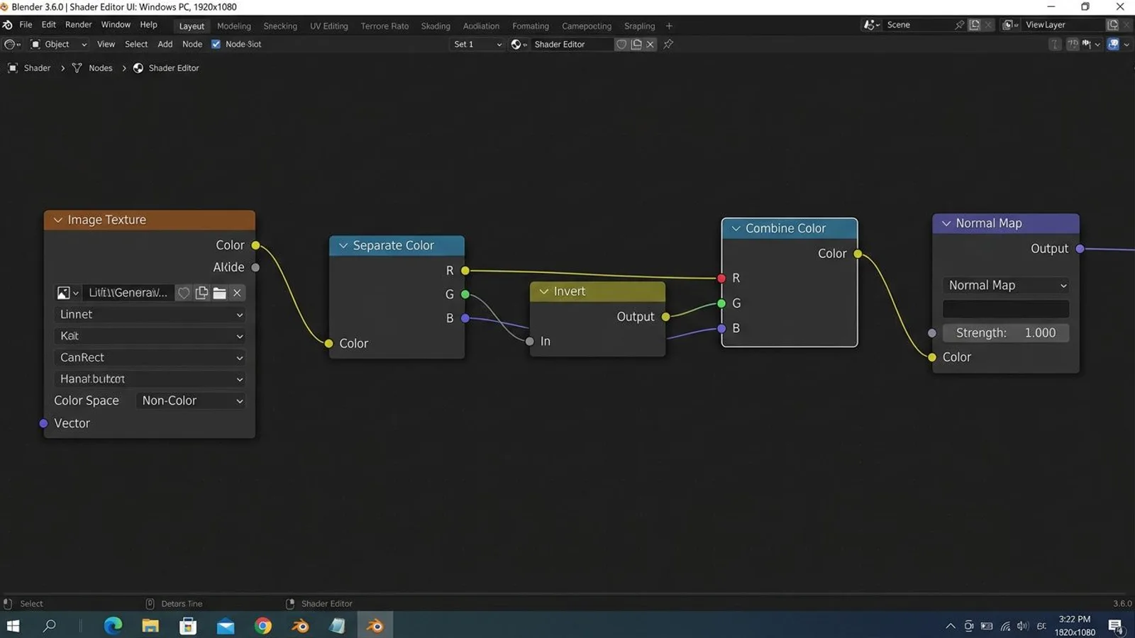
If you don't have a map with a working Convention option, or you want the flip visible in the node chain itself, work through the color channels directly. Add a Separate Color node (Mode RGB) after the Image Texture node, which gives you Red, Green, and Blue separately. Run the Green output through an Invert node or a Map Range node set up to produce 1 minus Green. Then feed Red, the inverted Green, and Blue back into a Combine Color node and connect its output to the Color input of the Normal Map node.
You'll see the result immediately in the viewport: recesses that used to look like bumps sit the right way round now. Save this small inversion chain as a node group if you work with foreign DirectX assets often, so you don't have to rebuild it every time.
The reason for the difference sits in how the map is built: the green channel encodes how strongly the surface tilts along the second tangent direction. OpenGL and DirectX define that direction exactly opposite to each other, which is why flipping just this one channel is enough. Red and Blue, the tilt along the first tangent direction and the height above the surface, stay identical in both conventions and don't need touching.
 AI-generated
Baking a normal map in Cycles
If you want to transfer detail from a high-resolution model onto a low-poly one yourself, you bake your own normal map. That requires Cycles as the active render engine, both models sitting in the same position on top of each other, and a low-poly model with a clean, non-overlapping UV map.
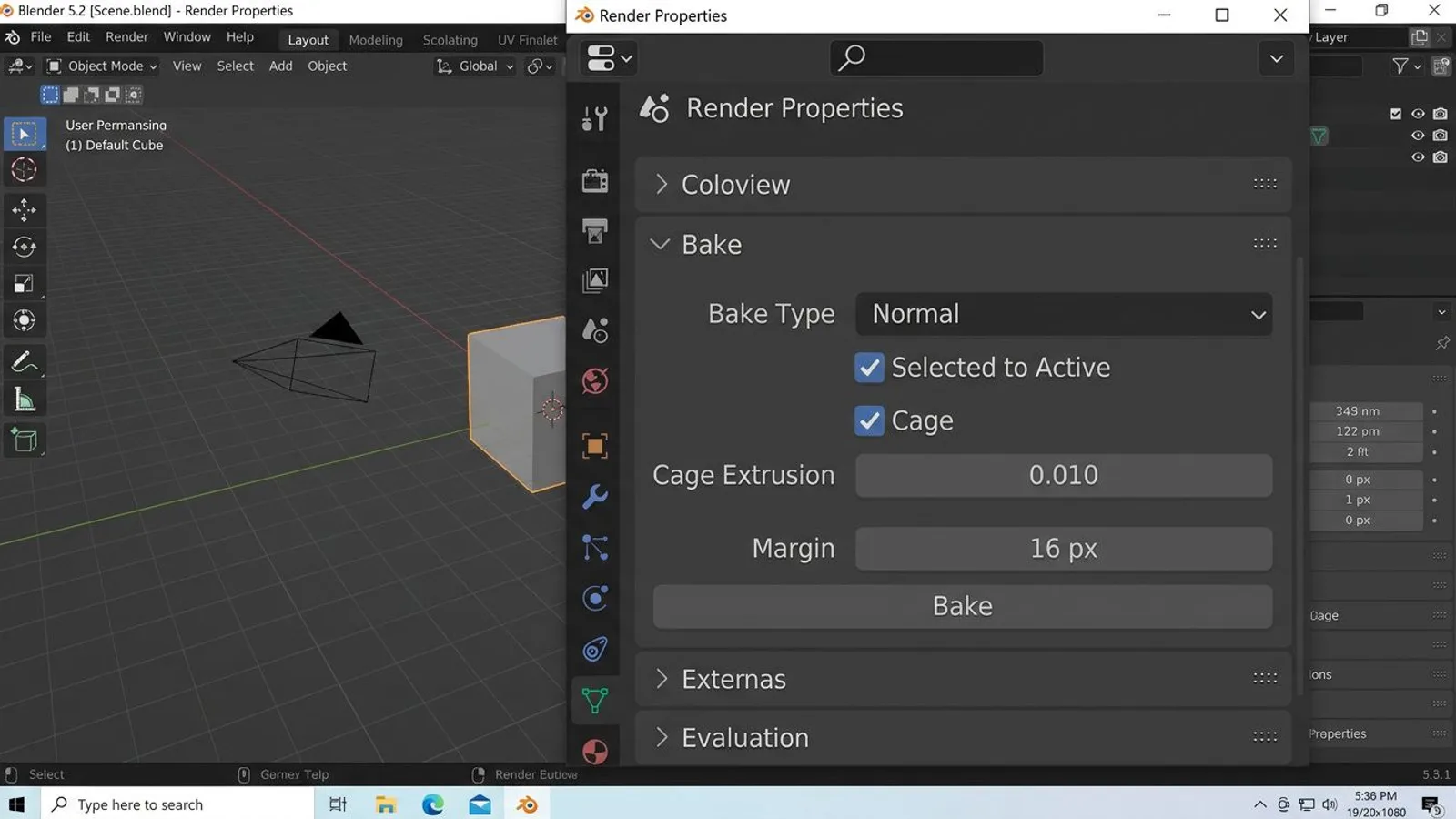
In the low-poly object's Shader Editor, first add a new Image Texture node, create a new empty image inside it at the resolution you want, and leave that node active and selected, since Blender always bakes into the most recently selected Image Texture node. Then switch to the Render Properties, Bake section, and set Bake Type to Normal.
Enable Selected to Active. Select the high-poly object first, hold Shift, and click the low-poly object last so it becomes the active object, since Blender bakes from the selected objects onto the active one. Leave Space on Tangent, which is the normal case and matches how we use the normal map in the material afterward.
If the two meshes don't line up exactly, the Cage option together with Cage Extrusion helps, or Max Ray Distance without a cage. Both control how far Blender searches inward and outward from the low-resolution surface to find the high-resolution geometry. Without a cage, Blender casts rays straight along the low-poly normals in both directions; with a cage, it instead uses a separately inflated copy of the low-poly mesh as the starting point, which usually gives cleaner results on irregular geometry. Cage Extrusion controls how far that copy expands outward.
Also watch the Margin, the extra border Blender paints around each UV island while baking. Too small a margin means neighboring UV islands can bleed into each other once mipmapping kicks in inside the engine, showing up as thin seams. A few extra pixels of margin cost almost no quality but save you trouble later. Finally, click Bake and save the resulting image externally, otherwise it's gone the moment you close the file.
For deep grooves or rows of rivets that need to show up in the actual silhouette, a normal map alone stops being enough, no matter how cleanly it's baked. That takes real geometric displacement instead, which we cover step by step in our displacement guide.
 AI-generated
Common problems
| Problem | Cause | Fix |
|---|---|---|
| Surface looks completely flat, no visible effect | Color space is set to sRGB instead of Non-Color, or the Normal Map node is missing | Set the color space to Non-Color, and route the image through a Normal Map node instead of connecting it directly |
| Bumps look inverted, recesses look like they stick out | DirectX convention instead of OpenGL, green channel is flipped | Set Convention to DirectX on the Normal Map node, or manually invert the green channel with Separate/Combine Color |
| Visible seams at UV boundaries | UV islands are packed too tightly, or the bake margin is too small | Increase the Margin in the Bake panel and pack UV islands with a bit more spacing |
| Baked map comes out black or heavily blotchy | High-poly and low-poly sit too far apart, rays cast during baking miss the surface | Increase Cage Extrusion or Max Ray Distance in the Bake panel, or try baking without a cage as a test |
| The Bake button won't do anything | No active Image Texture node selected in the material, or the render engine isn't set to Cycles | Set the render engine to Cycles and click the target Image Texture node in the Shader Editor before hitting Bake |
Frequently asked questions
Do I need to convert your normal map for Blender?
No. Our `_nor_gl` files use the OpenGL convention, which is exactly what Blender uses by default for rendering and baking. You only need to set the color space on the Image Texture node to Non-Color.
How do I recognize a DirectX normal map?
You can barely tell by eye, you either need to know the source or test it. If recesses look like bumps and the other way around, the green channel is flipped, that's the classic sign of a swapped convention.
How do I flip a DirectX map in Blender?
Either through the Normal Map node's own Convention property, set to DirectX if that option is available, or by using Separate Color and Combine Color to invert the green channel (1 minus green) and reassemble it.
What do I need to bake my own normal map?
A high-poly and a low-poly model in the same position, a UV map on the low-poly model, a new empty image as the bake target, and the Cycles render engine with Selected to Active enabled.
Why does my baked normal map come out black or blotchy?
Usually the distance between high-poly and low-poly is off, so the rays cast during baking miss the high-resolution surface. Adjust Cage Extrusion or Max Ray Distance in the Bake panel, a small positive value usually fixes it.